
ESP8266 - MAX6675 Thermocouple Module
Most of the temperature sensors we cover in other tutorials - the DHT11/DHT22, the DS18B20, the LM35 - top out somewhere between 100°C and 150°C. That's plenty for weather stations, incubators, or a kitchen gadget, but it's useless if you need to keep an eye on a pottery kiln, a wood-fired oven, a metal casting furnace, or the exhaust of a small engine, all of which run far hotter than any of those chips can survive.
For jobs like that, you need a completely different kind of sensor: a thermocouple. This tutorial walks through wiring a MAX6675 thermocouple module to an ESP8266 board and reading temperature over its 3-wire digital interface.
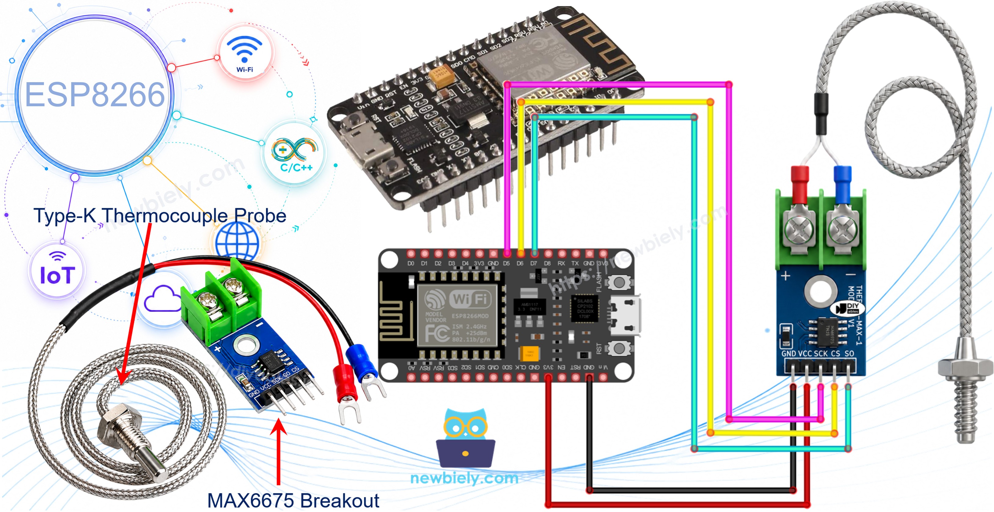
Hardware Preparation
Or you can buy the following kits:
| 1 | × | DIYables Sensor Kit (18 sensors/displays) |
Additionally, some of these links are for products from our own brand, DIYables .
How a Thermocouple Works
A thermocouple is simply two different metal wires welded together at one end. That joint is called the hot junction, and once it gets hot, it generates a very small voltage that rises and falls along with the temperature. It's a crude trick, but a very effective one - since there are no delicate silicon components sitting in the heat, a thermocouple can survive temperatures that would instantly destroy a regular electronic sensor.
Several thermocouple types exist, named with letters (J, K, E, T, and so on) depending on which two metals are welded together. Type-K is by far the most common, built from Chromel and Alumel wires, and it covers an enormous span of roughly -328°F to +2300°F.
The catch is that the voltage coming off a thermocouple junction is tiny - just a few millivolts - and turning that into a usable temperature reading takes a dedicated chip. That's the job of the MAX6675.
Overview of MAX6675 Module
The MAX6675 module you'll find sold online is a small breakout board built around the MAX6675 IC, bundled together with a Type-K thermocouple probe.
MAX6675 Module Pinout
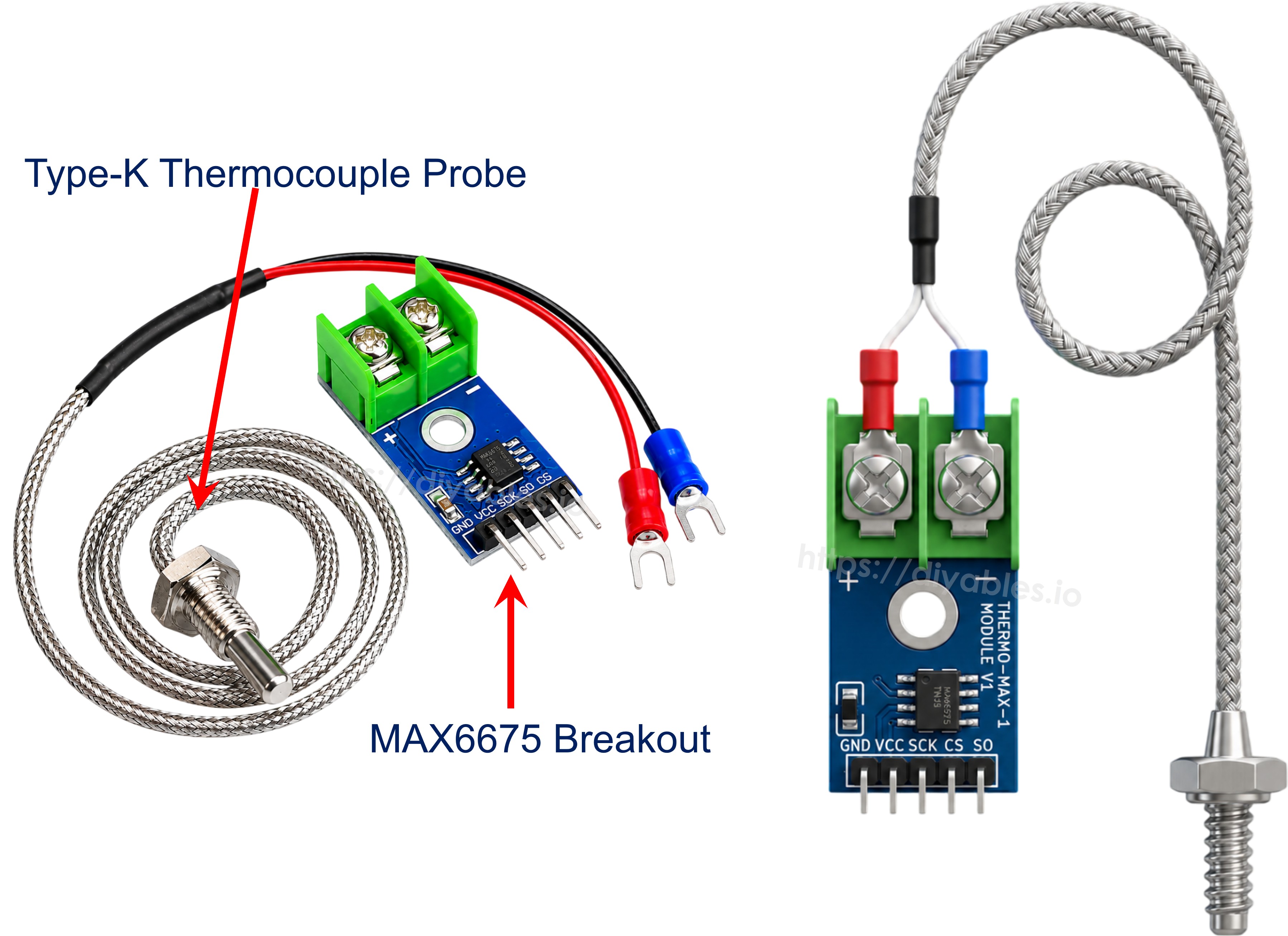
Internally, the MAX6675 samples the thermocouple's voltage, runs it through a 12-bit analog-to-digital converter, and makes the result available over a simple 3-wire read-only interface. There's no MOSI line here because the ESP8266 never has to send data to the chip - it only ever reads:
- VCC: power pin, accepts anywhere from 3.0V to 5.5V.
- GND: ground pin.
- SCK: serial clock, driven by the ESP8266 to shift out each reading.
- CS: chip select - pulled low whenever the ESP8266 wants to take a reading.
- SO: serial data output (this is the module's MISO line) - carries the 12-bit reading back to the ESP8266.
On the opposite edge of the board sits a small screw terminal for the probe: the red wire clamps into the + slot and the blue wire into the - slot.
The probe itself is roughly 18 inches of cable ending in a metal tip, and although the MAX6675 chip can digitize readings all the way up to 1024°C, the probe that comes bundled with the module is only rated for 0-80°C. If your project needs to measure hotter than that, you'll need to pair the MAX6675 breakout with a higher-temperature-rated Type-K probe sold separately.
Quick specs:
- Operating Voltage: 3.0V - 5.5V
- Interface: 3-wire digital (SCK / CS / SO)
- Digitized Range: 0°C to 1024°C (bundled probe limited to 0-80°C)
- Accuracy: ±3°C
- Resolution: about 0.25°C
Wiring Diagram
The MAX6675 module is a 3.3V-5V part, but the ESP8266 itself is strictly a 3.3V board - its GPIOs are not 5V-tolerant. So power the module's VCC pin from the ESP8266's 3.3V pin, never from 5V, and wire GND to GND. Then pick any three free GPIOs for SCK, CS, and SO.
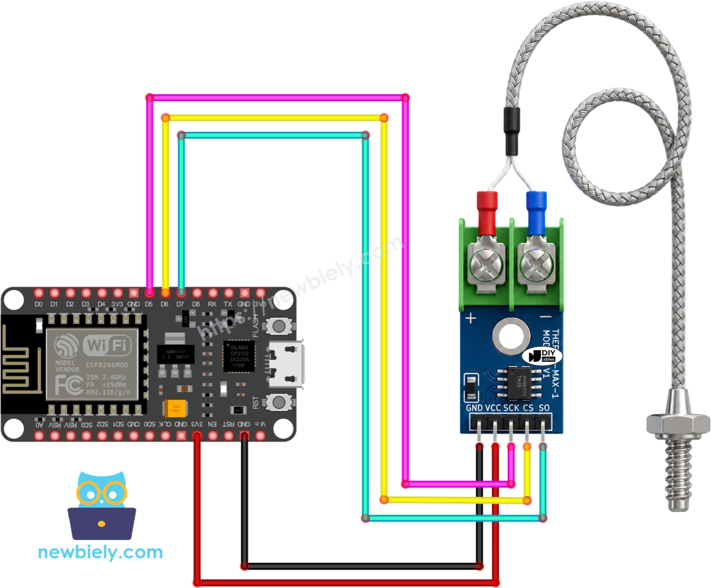
This image is created using Fritzing. Click to enlarge image
See more in ESP8266's pinout and how to supply power to the ESP8266 and other components.
Wiring table of MAX6675 Module and ESP8266 NodeMCU
| MAX6675 Module | ESP8266 NodeMCU |
|---|---|
| VCC | → 3.3V |
| GND | → GND |
| SCK | → D5 |
| CS | → D6 |
| SO | → D7 |
ESP8266 Code
Detailed Instructions
- If this is your first time working with the ESP8266, start with the environment setup for ESP8266 on Arduino IDE tutorial.
- Wire the MAX6675 module to the ESP8266 NodeMCU following the table and diagram above.
- Clip the thermocouple probe's + and - wires into the module's terminal block if you haven't already.
- Plug the ESP8266 into your computer with a USB cable.
- Open the Arduino IDE, pick the correct ESP8266 board entry (e.g. NodeMCU 1.0 (ESP-12E Module)) and the matching COM port.
- Open the Libraries panel from the left sidebar.
- Search "MAX6675" and find the library published by Adafruit.
- Click Install to add it to your IDE.
- Search for MAX6675 library created by Adafruit and click the Install button.
- Paste the code above into a new sketch.
- Press Upload to flash the sketch onto the ESP8266.
- Hold the tip of the probe against something warm (a mug of coffee, your fingertip, a hair dryer at a safe distance) and watch the numbers move.
- Open the Serial Monitor to watch the live readings.
※ NOTE THAT:
Getting no reading, a frozen value, or a wildly wrong temperature almost always traces back to wiring: double-check SCK/CS/SO match the pins in the sketch, and confirm the probe's + and - wires are seated firmly in the terminal block rather than just resting against it.
Code Explanation
The sketch pulls in the MAX6675 library, which handles all the bit-banged communication with the chip for us.
Three pins are defined for the ESP8266 side of the link - the clock line, the chip-select line, and the data-out line coming from the module.
A single MAX6675 object named thermocouple is constructed, telling the library which pin plays which role.
setup() just opens the Serial connection and pauses briefly, giving the module a moment to settle before the first conversion is requested.
Inside loop(), the two library functions readCelsius() and readFahrenheit() each trigger a fresh read from the chip and hand back the temperature in the requested unit.
Both values are then printed to the Serial Monitor on one line, followed by a one-second pause - which comfortably matches the MAX6675's own internal conversion rate, so we're never polling faster than it can actually produce new data.