
ESP8266 - PC817 Optocoupler: Monitor 12V/24V DC Input Signal
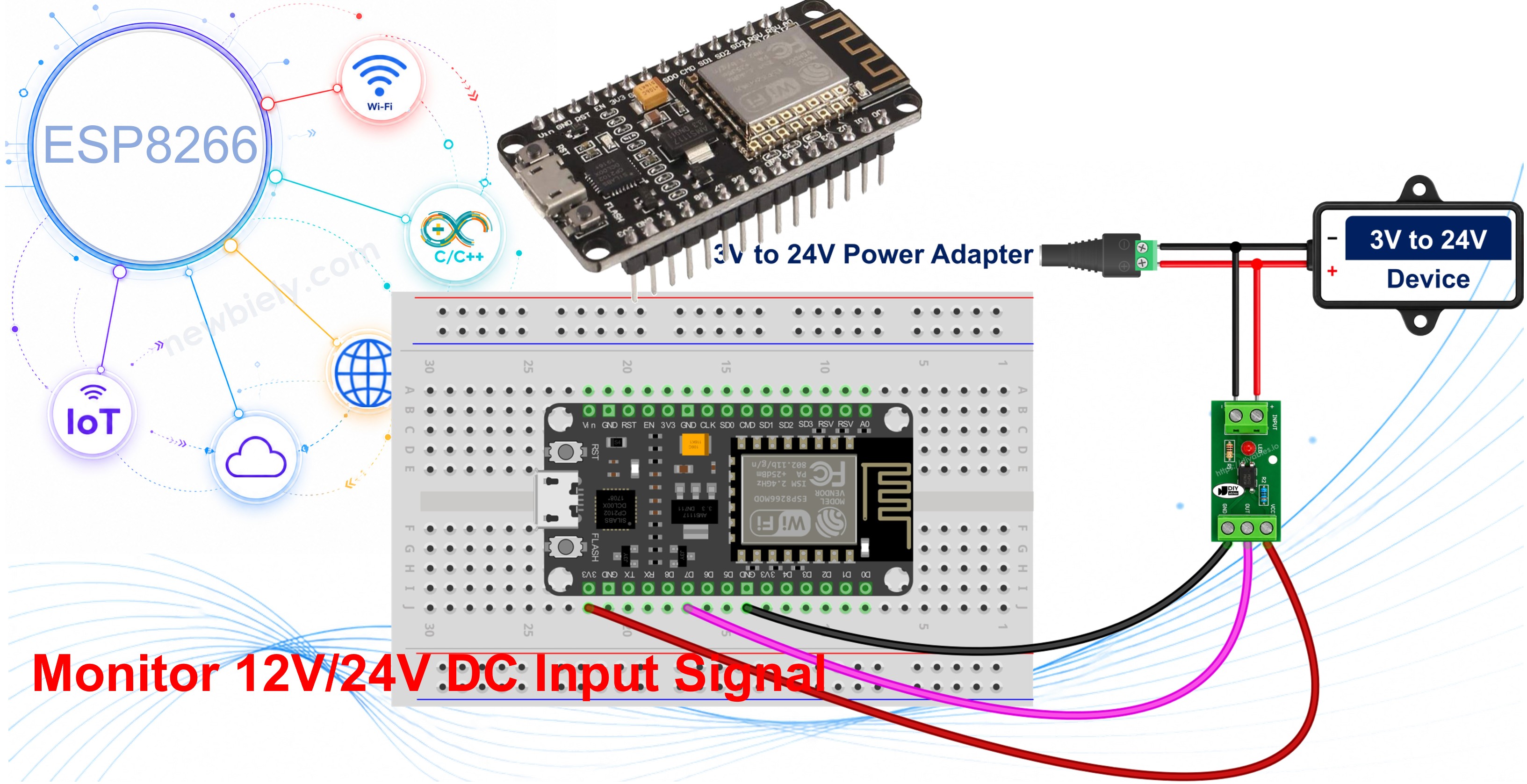
A PC817 optocoupler module lets the ESP8266 watch a 12V or 24V line without ever touching it electrically, which matters a great deal on a board whose pins are rated for 3.3V only. This tutorial instructs you how to use ESP8266 to read an isolated digital input built around the PC817, and how to tap that input across a piece of equipment so the board can answer the question you actually care about: is that device running right now, or not? In detail, we will learn:
- What a PC817 optocoupler module is and what each of its terminals does.
- Which of the three module variants - 12V, 24V or 3-5V - matches the line you want to watch, and what goes wrong if you buy the other one.
- How to connect a PC817 optocoupler module to ESP8266, and how to build the same input from the bare four-pin chip instead.
- How to wire the module in parallel across the device you want to watch, without cutting or rerouting a single existing wire.
- Which ESP8266 GPIO pins are safe to use for this job, and why the boot-strapping pins are not.
- How to find out whether your module reports active-LOW or active-HIGH, and how to flip the sketch with a single constant.
We suggest:
Hardware Preparation
Or you can buy the following kits:
| 1 | × | DIYables Sensor Kit (18 sensors/displays) |
Additionally, some of these links are for products from our own brand, DIYables .
Overview of PC817 Optocoupler
The PC817 is a four-pin chip that carries a digital signal from one circuit to another using light rather than a wire. Inside the plastic body there is an infrared LED facing a phototransistor across an insulating gap: when current flows through the LED, its light switches the transistor on, so the signal crosses as light instead of electricity. That gap is the reason the two sides stay electrically separate, and it is rated at 5000 Vrms for one minute.
For the ESP8266 this separation is not a luxury. The ESP8266 runs at 3.3V and its GPIO pins are not 5V tolerant, so a 12V or 24V wire touched directly to a pin destroys the chip. With a PC817 in between, the 24V side and the 3.3V side never share a single conductor.
Almost nobody solders the bare chip for this job any more. A PC817 optocoupler isolation module puts the same chip on a small board together with its series resistor, a status LED, screw terminals for the dangerous side and a header for the ESP8266 side, so the whole isolated input becomes three wires and two screws. This tutorial is built around that module; the bare chip is kept further down for anyone who would rather build it themselves.
Specifications of the PC817 inside the module:
| Item | Value |
|---|---|
| Package | 4-pin DIP, pin 1 marked by a dot or a notch |
| Input LED forward voltage (Vf) | about 1.2 V typical, 1.4 V max |
| Input LED forward current (If) | 20 mA continuous max, 5-20 mA normal, 10 mA a good target |
| Output collector-emitter voltage (VCEO) | 35 V max |
| Output collector current (IC) | 50 mA max |
| Collector power dissipation | 150 mW |
| Isolation voltage | 5000 Vrms for 1 minute |
| Current Transfer Ratio (CTR) | 50% to 600% depending on rank (A 80-160%, B 130-260%, C 200-400%, D 300-600%) |
| Switching speed | rise time about 4 us, fall time about 3 us |
| Operating temperature | -30 C to +100 C |
The PC817 Optocoupler Module Pinout
The module has an input side and an output side, and nothing electrical crosses between them.
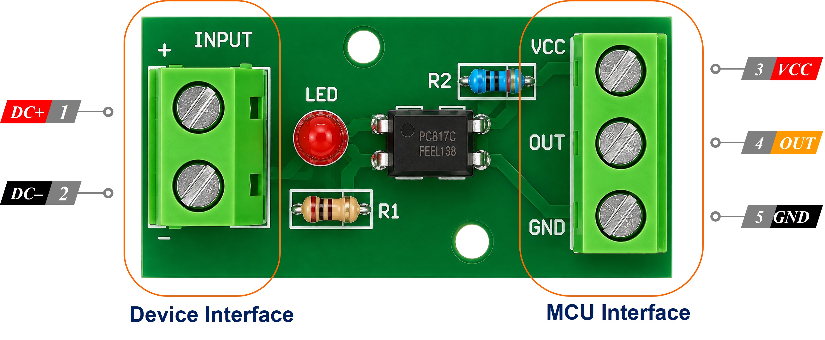
- Terminal IN+ (or +) - the positive of the input side. The switched positive of the 12V or 24V line you want to watch must be connected to this screw terminal.
- Terminal IN- (or -) - the negative of the input side. It must be connected to the return of that same external circuit, NOT to the ESP8266 GND.
- Pin VCC - the supply for the output stage. It must be connected to the ESP8266 3.3V pin.
- Pin GND - the ground of the output side. It must be connected to the ESP8266 GND pin.
- Pin OUT (labelled DO, or OUT1..OUTn on multi-channel boards) - the isolated output. It must be connected to an ESP8266 digital input pin that has a usable internal pull-up.
※ NOTE THAT:
The pin arrangement of optocoupler isolation modules varies between manufacturers. Some boards place VCC in the middle, some reverse GND and OUT, and some silkscreen the input terminals as IN and GND instead of + and -. Always read the labels printed on the board you actually bought instead of copying a photo. The input voltage a board is built for is usually printed there too, beside or under the screw terminals, and that is the quickest way to confirm you received the variant you ordered.
Which Optocoupler Module Do I Need For A 12V Or 24V Line?
This is the one purchase decision that matters, so make it before you order. The series resistor is already fitted on the module, and that resistor is sized for ONE input voltage - which is exactly why these boards are sold as three separate variants:
- 12V module - for a 12V DC signal. This is the variant for the boiler and immersion-heater example that this page keeps coming back to.
- 24V module - for a 24V DC signal: an alarm panel's siren output, a 24V PLC output, a 24V solenoid or contactor circuit.
- 3-5V module - for 3.3V and 5V logic signals. Worth having whenever the two circuits run from separate supplies, sit far apart on a long cable, or one of them is electrically noisy - a stepper driver, a motor controller, or the low-voltage control board buried inside a mains-powered appliance. Isolation is about breaking the ground path, not only about surviving a high voltage.
Buy the one that matches your line, and only that one. The variants are NOT interchangeable:
- A 12V module fed from a 24V line sees roughly double the LED current it was built for, and its input LED will be damaged.
- A 24V module fed from a 12V line underdrives its LED, so the output may switch late, switch unreliably, or never switch at all - the nastier of the two failures, because it can pass a bench test and then quietly miss events in the cabinet.
Note also that the PC817 input cares about current, not about how much the supply could deliver: a 12 V rail capable of many amps is no harder on the LED than one capable of milliamps, because the on-board resistor fixes the LED current either way. With a module there is nothing to work out - choosing the variant IS the resistor calculation, already done for you at the factory.
How It Works
The two halves of the module do nothing but exchange light:
- External 12V/24V signal PRESENT: current flows in the input LED, the on-board status LED lights, and the phototransistor conducts.
- External 12V/24V signal ABSENT: the input LED is dark, the status LED is out, and the phototransistor is off.
What that does to the OUT pin, and therefore to the value the ESP8266 reads, is the subject of the next section.
Is Your Optocoupler Module Active High Or Active Low?
On the bare chip this is settled physics. The phototransistor can only pull a pin DOWN, so with the ESP8266 pull-up holding the pin HIGH, a live external line reads LOW and a dead one reads HIGH - the reading is INVERTED.
On a module you have to check, because module output polarity varies between manufacturers. Many boards bring the phototransistor's collector straight out, so OUT behaves like the bare chip and goes LOW when the input is energised. Others invert it on the board, so OUT FOLLOWS the input and goes HIGH when the input is energised. Both kinds are sold, sometimes under the same product photograph, so the only reliable answer is the one your own board gives you.
The test takes less than a minute:
- Wire the module to the ESP8266 as shown below and upload the sketch from this tutorial.
- Open the Serial Monitor with nothing connected to IN+ and IN-, and note what it prints.
- Energise the external line, and note what it prints now.
- Whichever state appears WHILE the signal is present is your module's active level.
- Use the on-board status LED as the cross-check. It lights whenever the input side is energised, so if the LED is clearly lit and the Serial Monitor still says IDLE, your polarity assumption is the wrong way round.
Correcting it is one edit, not a rewrite. The sketch below carries a single constant:
Leave it true for a module whose output goes LOW while the signal is present, set it to false for a module whose output goes HIGH, and everything downstream follows.
Building The Isolated Input From The Bare PC817 Chip (Optional)
If you would rather build it from the raw chip, the PC817 is a 4-pin DIP with pin 1 at the corner marked by a dot or a notch, numbered anticlockwise from above.
- Pin 1 - Anode (A) and Pin 2 - Cathode (K): the input LED. The external positive must be connected to pin 1 through a series resistor, and pin 2 must be connected to the ground of the external circuit ONLY.
- Pin 3 - Emitter (E): must be connected to the ESP8266 GND pin.
- Pin 4 - Collector (C): must be connected to the ESP8266 input pin, which supplies the pull-up.
Here the LED current is yours to set, with R = (Vin - 1.2) / 0.01 for a 10 mA target: 220 ohm at 3.3 V, 390 ohm at 5 V, 1 kohm at 12 V, and 2.2 kohm at 24 V - the last of those dissipates about 0.24 W, so use a 1/2 W part. The bare chip is always active-LOW, so leave MODULE_ACTIVE_LOW set to true.
The Isolation Rule
Do NOT connect the ground of the 12V/24V circuit to the ESP8266 GND pin, and do not connect it to the module's GND header pin either. Those two grounds must stay apart, and that separation is the entire reason the PC817 is there. If you tie them together, the optocoupler keeps switching and everything appears to work, but the isolation is gone and a fault on the 24V side now has a path straight into your 3.3V board.
Wiring Diagram
The sketch in this tutorial uses pin D7 (GPIO13) for the isolated input. On the ESP8266 that choice is not arbitrary: D7 is one of the plain, boot-safe GPIOs and it has a usable internal pull-up, which is exactly what an active-LOW optocoupler output needs. Pin D0 (GPIO16) is the one pin that has no internal pull-up at all, and pins D3 (GPIO0), D4 (GPIO2) and D8 (GPIO15) are boot-strapping pins whose level at power-up decides how the chip starts. Use the NodeMCU Dx labels in your sketch rather than the raw GPIO numbers, because on a NodeMCU board D7 resolves to GPIO13 for you while writing 13 literally means GPIO13 and does not match the silkscreen.
- Wiring diagram between ESP8266 and a PC817 optocoupler isolation module
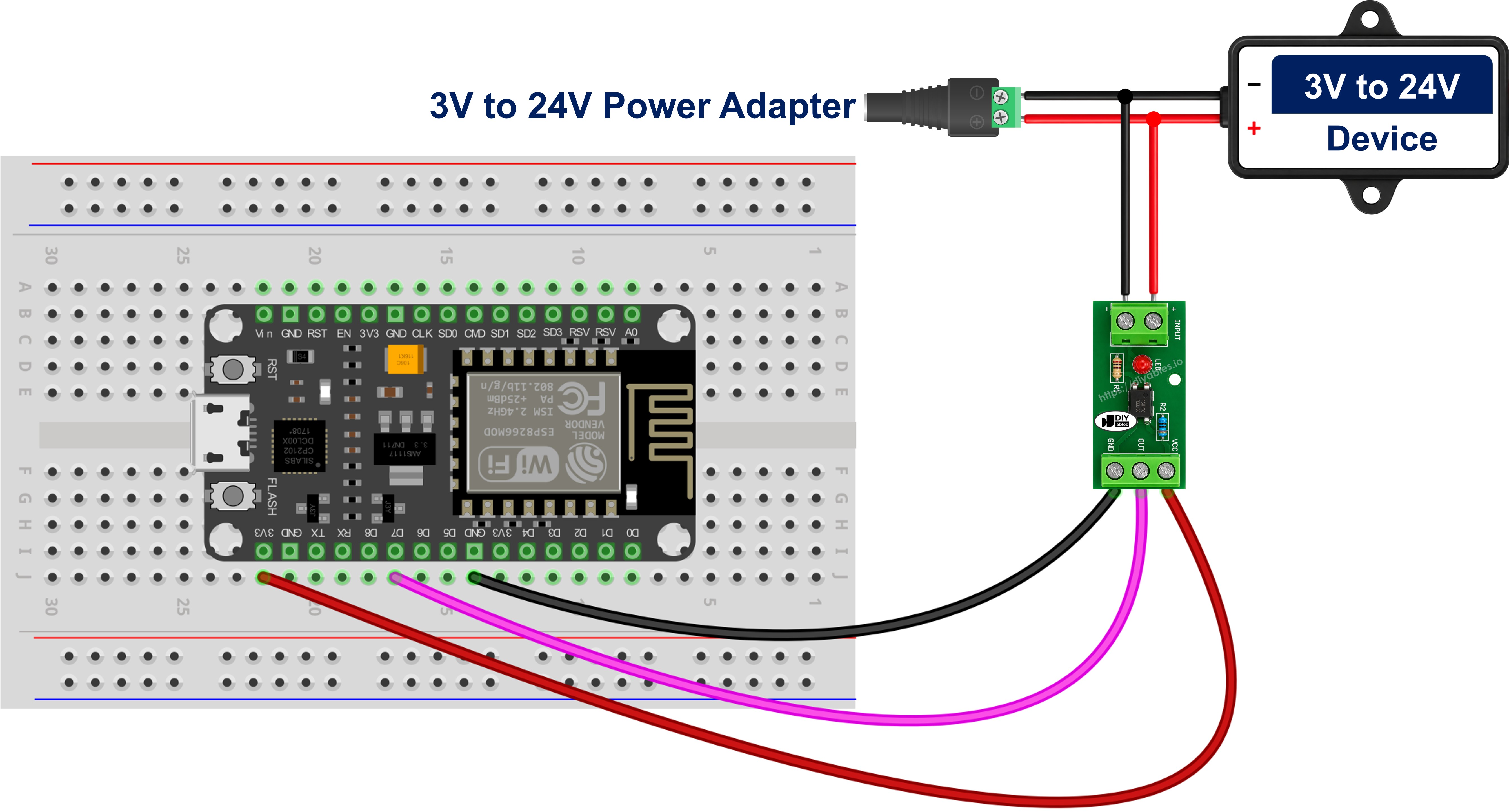
This image is created using Fritzing. Click to enlarge image
See more in ESP8266's pinout and how to supply power to the ESP8266 and other components.
Wire the external line into the IN+ and IN- screw terminals, then connect the module's VCC to the ESP8266 3.3V pin, GND to the ESP8266 GND pin, and OUT to ESP8266 D7. Power the module's output side from 3.3V rather than from 5V or Vin, because whatever the module's output stage is powered from is what appears on the ESP8266 pin, and the ESP8266 is not 5V tolerant. There is no resistor to fit and no current to work out - that was settled when you chose the 12V, 24V or 3-5V variant. Once it is wired, run the one-minute test above to learn which way round your module's output is.
- Wiring diagram between ESP8266 and the bare PC817 chip
On the bare-chip route, the positive of the 12V or 24V signal goes through the series resistor (1 kohm for 12 V, 2.2 kohm for 24 V) into pin 1, and pin 2 returns to the ground of that external circuit only. On the output side, pin 4 goes to ESP8266 D7 and pin 3 goes to ESP8266 GND. The pull-up is switched on in software, so no extra resistor is needed on the 3.3V side.
Wiring The PC817 In Parallel To Monitor Whether A Device Is On Or Off
Both diagrams above show a bare 12V or 24V signal, but in a real installation that signal already belongs to something. On the heating example this page keeps coming back to, it is the call-for-heat line that a room thermostat closes to start a boiler or an immersion heater. To watch that line, the module's input goes ACROSS it, in parallel with the device, and never in series with it. An optocoupler put in series would carry the whole load current - the boiler's contactor coil, or on a direct immersion circuit the element itself - through an infrared LED rated at 20 mA, and the PC817 would be destroyed the first time the thermostat called for heat.
The tap is two screws, and it cuts nothing:
- The positive, switched terminal of the device goes to the module's IN+ terminal.
- The negative or return terminal of the device goes to the module's IN- terminal.
- Every existing wire stays exactly where the installer left it.
Nothing goes in between. The series resistor that the bare chip would need is already on the board, sized for the variant you bought, and that is the whole convenience of the module: a parallel tap becomes two screw connections and no arithmetic.
The tap draws only about 10 mA, which is nothing beside a contactor coil, a valve, a lamp or a pump motor, so the device carries on working exactly as it did before it was watched. That keeps the measurement read-only, and it also keeps it honest: because the optocoupler sits across the device instead of in front of it, the reading follows the device's own state whoever commanded it. A boiler timer, a frost stat, a cylinder thermostat or a hand on the wall control all show up on the Serial Monitor, and so does a call that goes out and gets no response at all. Run-hour counters, idle-time logs and "did it actually fire?" alerts all fall out of that single parallel tap.
Three details decide whether it works on the first attempt:
- Polarity of the tap. The input side is a plain LED and conducts in one direction only. Swap IN+ and IN- and nothing is damaged, but the optocoupler simply never switches on and the status LED never lights, so establish which side of the tap is positive before you strip any insulation.
- Leakage. Some PLC transistor outputs, triac outputs and LED-lamp drivers pass a small current even while switched off, and enough of it partly lights the PC817 LED. The symptom is unmistakable: the reading goes ENERGISED and never returns to IDLE. Fit a bleeder resistor of about 4.7 kohm to 10 kohm across the module's IN+ and IN- terminals, so that leakage flows through the resistor instead of the LED.
- DC only. The PC817 input is a single LED, so it answers to one polarity; sensing an AC line calls for an optocoupler whose input stage carries two back-to-back LEDs instead.
※ NOTE THAT:
Any inductive load - a relay or contactor coil, a solenoid, a motorised valve, a circulating pump - produces a large reverse-voltage spike as it switches off, and the PC817 input LED withstands only 6 V in reverse. Fit an ordinary diode in reverse-parallel directly across the module's input terminals, with the diode cathode to IN+ and the diode anode to IN-. While the device runs, that diode is reverse-biased and does nothing at all; on a spike it conducts and clamps the reverse voltage to well under a volt. A 1N4148 covers small taps, a 1N4007 the heavier ones.
What An Energised Reading Proves, And What It Does Not
One limitation is worth stating plainly: the tap tells you the device is energised, not that it is doing its job. An immersion heater with a burnt-out element still pulls its call-for-heat line down and still reads as ON, exactly as a seized pump or a stalled fan would. What the ESP8266 can do with that is compare cause and effect - two hours energised with nothing to show for it is a useful alarm in its own right, as long as you remember it is an inference and not a measurement.
How To Program For PC817 Optocoupler
The first step is to configure the chosen ESP8266 pin as an input with the internal pull-up enabled, which is what keeps the pin at a defined HIGH while an active-LOW optocoupler output is idle:
The second step is to read the pin with the digitalRead() function:
The third step is to turn that raw level into a meaning, using the one constant that carries your module's polarity:
The final step is to act on that boolean. Comparing it with the previous reading, rather than printing on every pass of loop(), keeps the Serial Monitor readable and gives you one line per real change on the 12V/24V line.
ESP8266 Code for PC817 Optocoupler
Detailed Instructions
To get started with ESP8266 on Arduino IDE, follow these steps:
- Check out the how to setup environment for ESP8266 on Arduino IDE tutorial if this is your first time using ESP8266.
- Check that your module variant matches your input voltage: the 12V module on a 12V line, the 24V module on a 24V line, the 3-5V module on a logic-level signal.
- Wire the components as shown in the diagram, keeping the 12V/24V ground away from the ESP8266 GND.
- Connect the ESP8266 board to your computer using a USB cable.
- Open Arduino IDE on your computer.
- Choose the correct ESP8266 board (e.g. NodeMCU 1.0 (ESP-12E Module)), and its respective COM port.
- Copy the code above and open it in the Arduino IDE.
- Click the Upload button on the Arduino IDE to compile and upload the code to the ESP8266.
- Open the Serial Monitor.
- Switch the external 12V/24V line on and off a few times.
- Check out the result on the Serial Monitor.
If the Serial Monitor reports the opposite of what the module's status LED is doing, you have an active-HIGH module: set MODULE_ACTIVE_LOW to false and upload again.
Because the ESP8266 only ever sees an open or closed transistor, the same sketch and the same wiring work for a 12 V source and a 24 V source. The only thing that changes between them is which module variant you bought.
Two projects this circuit suits well:
- A cheap always-on heating monitor: a 12V module watches the 12 V call-for-heat line between a room thermostat and a boiler or an immersion heater, and the ESP8266 logs how many minutes per day the heat is actually being demanded, without any modification to the heating wiring itself.
- A 24 V alarm siren watchdog: a 24V module sits across the 24 V siren output of an alarm panel, so the ESP8266 knows the moment the panel fires, and the panel keeps its own isolated ground.
- A general device on/off monitor: tapped in parallel across any DC-fed pump, valve, contactor or lamp, the same circuit becomes a run-hour counter, a machine idle-time log, and a "the controller asked for it but nothing started" alert.
Code Explanation
Check out the line-by-line explanation contained in the comments of the source code!
Video Tutorial
Additional Knowledge
Choosing the pin is the part of this project that is specific to the ESP8266, and it is worth getting right before you screw anything down.
The ESP8266 exposes roughly eleven usable GPIO pins, and they are not interchangeable. Five of them behave like ordinary digital inputs with a working internal pull-up: D1 (GPIO5), D2 (GPIO4), D5 (GPIO14), D6 (GPIO12) and D7 (GPIO13). Any one of these is a good home for an optocoupler output.
Three others are boot-strapping pins. GPIO0 (D3) and GPIO2 (D4) must be HIGH when the board powers up, and GPIO15 (D8) must be LOW. An optocoupler whose external line happens to be live at the instant you apply power holds its output LOW, so putting it on D3 or D4 can drop the board into flash mode instead of running your sketch. The failure looks random, because it depends on whether the 12V/24V line was energised at power-up, which makes it a miserable bug to chase.
GPIO16 (D0) fails for a different reason. It is a separate pin on the chip and, unlike the others, it has no internal pull-up: INPUT_PULLUP is not available on it, only INPUT_PULLDOWN_16. Since a bare phototransistor can only pull a pin down, a pin that cannot be pulled up has nothing to be pulled down from, and the reading floats. If you truly must use D0 with the bare chip, add an external 10 kohm resistor from the pin to 3.3V and configure the pin as a plain INPUT.
Using a module rather than the bare chip moves those two problems in opposite directions. A module whose output stage already carries its own pull-up drives the pin from both sides and does not depend on the ESP8266's internal pull-up at all, which softens the D0 objection - but only once you have confirmed from the board itself that yours is built that way, since plenty of modules bring the bare collector straight out to the header. The boot-strapping pins get no such relief. GPIO0 (D3) and GPIO2 (D4) need to be HIGH as the chip starts, so a module output sitting LOW at that instant can stop the board booting normally, and GPIO15 (D8) needs to be LOW, so a module output sitting HIGH there can do the same. Whether the output happens to be LOW or HIGH at power-up depends on the module's polarity and on whether the external line was live, neither of which you can arrange from software. Keep D3, D4 and D8 out of this circuit whichever kind of module you own.
The pull-up value itself is generous. The ESP8266 internal pull-up is in the tens of kilohms, which asks only a few tens of microamps of the phototransistor, far below the 50 mA it can sink and easily reached even by a low-CTR PC817 running at 10 mA on the LED side. An external 10 kohm resistor to 3.3V works just as well and is slightly more resistant to electrical noise on long cable runs, which is worth considering when the module is metres away in a control cabinet.
It is evident that the safest arrangement on this board is one of the plain D-numbered pins with INPUT_PULLUP enabled in software, referred to by its Dx label so the sketch matches the silkscreen. Everything else about the PC817 is the same on any microcontroller; the pin choice is the one decision the ESP8266 makes for you.