
ESP8266 - NTC Thermistor Temperature Sensor
The ESP8266 has just one analog input, and a thermistor probe needs just one. That makes the NodeMCU a good, cheap base for a WiFi thermometer in a water tank, a compost bin or next to a hot-water pipe. This tutorial instructs you how to hook a stainless-steel 10K NTC 3950 probe up to the ESP8266 NodeMCU and turn its changing resistance into degrees Celsius and Fahrenheit. In detail, we will learn:
- What the steel probe hides, and the job of the 10K resistor packed with it
- How to hook up the probe, its resistor and a NodeMCU sitting on a breadboard, using only the 3V3, A0 and GND pins
- How to program the ESP8266 to average ten A0 readings, find the probe's resistance, and get °C and °F out of it with the B (beta) formula
- Why 1023 on the A0 pin of the NodeMCU stands for about 3.2V, and what the board's own resistors do to the result
- How the sketch warns you about a loose plug or a short
We suggest:
- Utilizing the DS18B20 waterproof temperature sensor when you want the probe to send a finished digital value. It uses a digital pin, so A0 stays free for another analog sensor.
- Utilizing the MAX6675 thermocouple module for heat beyond 105°C, such as a pizza oven or a charcoal grill.
Hardware Preparation
Or you can buy the following kits:
| 1 | × | DIYables Sensor Kit (18 sensors/displays) |
Additionally, some of these links are for products from our own brand, DIYables .
Overview of NTC Thermistor Temperature Sensor
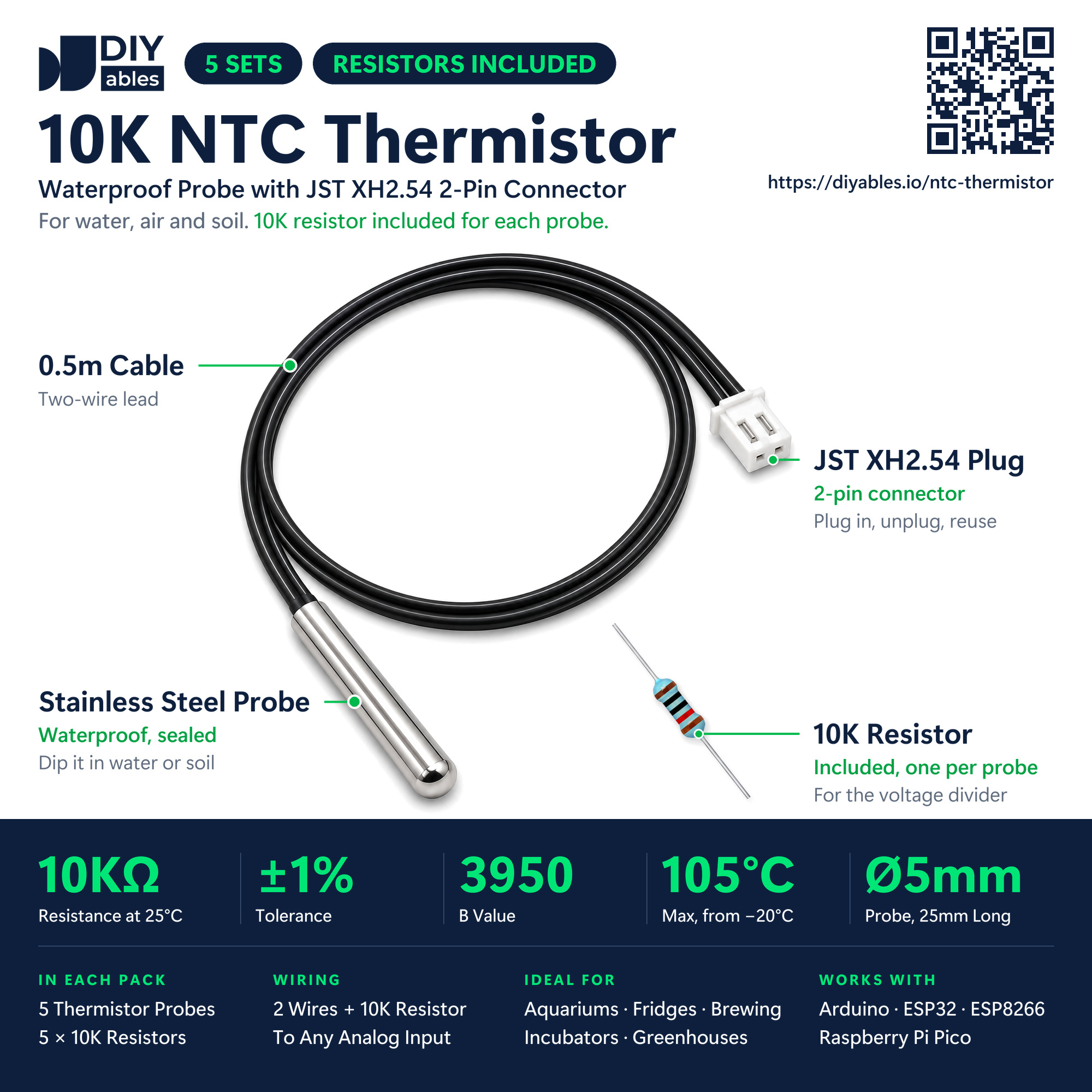
There is no module here, only a bare probe. Its business end is a stainless-steel sleeve, 5mm across and 25mm in length, closed by a rounded tip. One tiny 10K NTC thermistor is sealed inside. Half a meter of black two-wire cable leads away from the sleeve to a white 2-pin JST XH2.54 plug. You will find no PCB, no IC and no header pins on it. The DIYables pack holds five probes and five 10K resistors, one resistor for each probe. That resistor is part of the circuit below, so keep it together with its probe.
| 10K NTC 3950 Waterproof Probe | |
|---|---|
| Thermistor | NTC, 10kΩ at 25°C, ±1% |
| B constant | 3950 |
| Usable range | -20°C to 105°C |
| Sleeve | stainless steel, 5mm x 25mm, rounded tip, waterproof |
| Cable | 0.5m, two black wires |
| Plug | white JST XH2.54, 2 pins |
| Wire order | free, a thermistor has no polarity |
| Cable pull test | 9.8N (1kgf) for 1 minute |
| In the pack | 5 probes and 5 resistors of 10K |
From Heat to a Number on A0
In one sentence: a thermistor is a resistor that changes its value a lot when it gets warmer or colder, and the NodeMCU reads that value and turns it into degrees. NTC, short for Negative Temperature Coefficient, gives the direction: more heat, less resistance. This probe has 10,000 ohms at 25°C, more in the cold and less in the heat.
A0 understands volts, not ohms. To bridge that gap, the probe and the 10K resistor are chained from 3V3 down to GND, and A0 taps the joint between them. In this voltage divider, the probe is on top and the resistor at the bottom. When the tip heats up, the probe's share of the resistance shrinks, A0 moves up toward 3.3V, and analogRead() gives a higher count. Typical values with this wiring (rounded; your board can be a few counts off):
| Probe temperature | Probe resistance | Voltage on A0 | analogRead() on a NodeMCU |
|---|---|---|---|
| -5°C | about 44.0kΩ | 0.60V | about 190 |
| 12°C | about 18.3kΩ | 1.14V | about 365 |
| 33°C | about 7.1kΩ | 1.91V | about 610 |
| 55°C | about 3.0kΩ | 2.52V | about 807 |
| 75°C | about 1.5kΩ | 2.86V | about 914 |
The sketch runs this chain in reverse: count, then volts, then the probe resistance R. From R, the B-parameter (beta) equation finds the temperature T in kelvin:
1/T = 1/T0 + (1/B) × ln(R/R0)
For this probe, B = 3950, and R0 = 10000Ω belongs to T0 = 298.15K (that is 25°C). ln stands for the natural logarithm, written log() in a sketch. To go from kelvin to °C, the sketch subtracts 273.15. Other guides work with the Steinhart-Hart equation, which has three coefficients and fits the curve more closely. With a 1% probe like this one, the simpler B equation is all you need. Expect results within about 1°C near room temperature; how close you get also depends on the tolerance of the 10K resistor and on the ADC of the ESP8266.
The NTC Thermistor Temperature Sensor Pinout
The white plug has two openings and nothing printed next to them. Each opening takes the pin of one male jumper wire:
- Probe wire 1 (pick any): must be connected to 3V3 on the NodeMCU, never to VIN.
- The other probe wire: must be connected to A0, the only analog input on the ESP8266.
- The 10K resistor from the pack: must be connected across A0 and GND (0V). At the A0 end, it joins the probe wire.
※ NOTE THAT:
Since the thermistor inside is a plain resistor, either wire can take 3V3. That is why the plug has no marks and cannot go in backwards. The 10K resistor is different: its place is fixed, between A0 and GND. If the probe and the resistor trade places, the number on A0 falls when the tip gets warm, and the sketch prints wrong temperatures.
Wiring Diagram
In the diagram, the NodeMCU is plugged into a breadboard, and the 10K resistor is plugged into the same breadboard. The NodeMCU covers almost every hole next to its pins, so the resistor uses a free column on the left. It stands across the middle gap and joins the two halves of that column: the black wire brings GND from the G pin on the other long edge to the upper half, and the yellow wire brings A0 to the lower half. A second yellow jumper takes the A0 signal from that column to one opening of the white plug. The red wire takes 3V3 to the other opening.
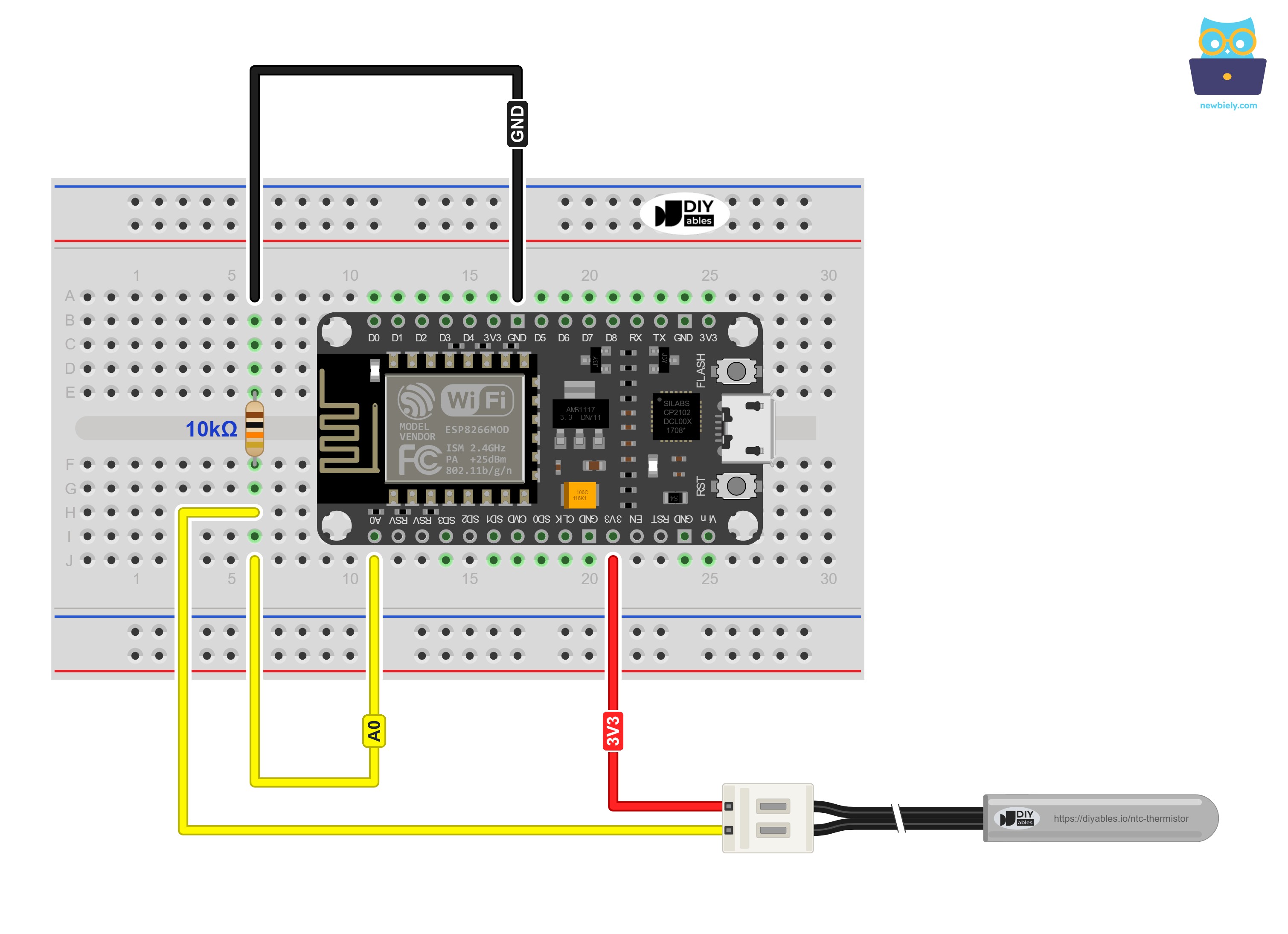
This image is created using Fritzing. Click to enlarge image
See more in ESP8266's pinout and how to supply power to the ESP8266 and other components.
| NTC Thermistor Circuit | ESP8266 NodeMCU Pin |
|---|---|
| Probe lead A (either lead) | → 3V3 |
| Probe lead B | → A0 |
| 10K resistor, one end | → A0 (through a free breadboard column) |
| 10K resistor, other end | → GND (G) |
WARNING
Feed the probe from 3V3, not from VIN. VIN carries the 5V of the USB port. A hot probe has very little resistance, so A0 would then climb close to 5V, far above the 3.3V the A0 pin of the NodeMCU is made for. The 3V3 pin is fed by the voltage regulator on the board, so it stays at a steady 3.3V even when the USB voltage moves a little. The sketch counts on that 3.3V.
How To Program For NTC Thermistor
The sketch needs no library: analogRead() and log() ship with the ESP8266 core.
- Begin by giving A0 a name and listing the numbers of the probe, the resistor and the board as constants:
- Take ten analogRead() samples of A0 and store their mean in raw. Leave a few milliseconds between the samples: calling analogRead() nonstop, with no pause at all, can disturb the WiFi of the ESP8266.
- Turn raw into the voltage on the A0 pin. The bare ESP8266 chip accepts only 0 to 1V, so the NodeMCU board puts a small voltage divider in front of it. Because of that, 1023 means about 3.2V on A0, not 3.3V:
- Calculate the present resistance of the probe in ohms. It hangs between 3.3V and A0, while the 10K resistor goes down from A0 to GND:
- Hand the ohms to the B formula, then convert kelvin into °C and °F:
If 1023 stood for exactly 3.3V, the resistance line would be the same as the well-known R_FIXED * (1023 / raw - 1). On the NodeMCU, that shortcut reads too warm in hot water, so this sketch takes the extra step through volts.
ESP8266 NodeMCU Code for NTC Thermistor Temperature Sensor
About once per second, the sketch below prints one line: the A0 average, the A0 voltage, the probe's ohms, and °C plus °F. Before any math, it checks the average. An average near 0 tells the sketch that the probe is missing: nothing pulls A0 up, so the 10K resistor holds it at GND. An average near 1023 points to touching probe wires or a missing 10K resistor. Either way, a short hint appears instead of a nonsense temperature.
Detailed Instructions
- First time with the ESP8266? Install the board package by following how to setup environment for ESP8266 on Arduino IDE.
- Put the NodeMCU on the breadboard and make the connections from the table: probe to 3V3 and A0, 10K resistor from A0 to GND.
- Connect the ESP8266 NodeMCU board to your computer using a USB cable.
- Open Arduino IDE on your computer.
- Select the board NodeMCU 1.0 (ESP-12E Module) and the port your NodeMCU shows up on.
- Paste the sketch into a new Arduino IDE window and click Upload.
- Start the Serial Monitor and choose 9600 baud in its speed box.
- Get two glasses ready: one with warm water from the hot tap, one with cold tap water. Let the first few lines show the room air. Next, dip the steel tip into the warm glass. When the numbers stop climbing, move it over to the cold one.
Lines one to three are taken in room air at roughly 21.6°C. In the warm glass, the resistance falls from about 11.6kΩ to 5.1kΩ, and the temperature climbs to about 40.7°C. In the cold glass, it goes the other way and ends near 13.6°C. Both times, the changes get smaller line by line: the steel sleeve has to warm up or cool down itself before the thermistor inside can follow. Write a value down only once the last few lines match.
A few things to keep in mind:
- Water is fine for the steel sleeve only. The plug, the breadboard with the resistor and the NodeMCU must stay dry.
- Stay at or below 105°C. A baking oven or a grill is a job for the MAX6675 thermocouple module.
When a line reads "A0 is close to 0", push both jumper pins deeper into the white plug and look at the 3V3 wire. When it reads "A0 is at the top of its range", check whether the 10K resistor really links A0 to GND, and that the two probe wires do not touch.
Additional Knowledge
What the NodeMCU Does to A0 Before the ESP8266 Sees It
The ADC inside the ESP8266 chip has one input, and that input accepts only 0 to 1.0V. To make it useful for 3.3V signals, most NodeMCU boards (and the Wemos D1 mini) add two resistors: 220K from the A0 pin to the chip, and 100K from the chip to GND. So 3.2V on A0 becomes 1.0V at the chip, which reads as 1023. This small divider affects the thermistor circuit in two ways:
- The scale. 1023 means about 3.2V, not 3.3V. A sketch that assumes 3.3V thinks A0 is a bit higher than it is, so it reads too warm. The hotter the probe, the closer A0 gets to the top of the scale, and the bigger this error grows. That is why the sketch uses A0_FULL_SCALE_V = 3.2.
- The load. The 220K and 100K together (320K) also lead from A0 to GND, right beside the 10K resistor. Side by side, they act like a resistor of about 9.7K instead of 10K. This pulls the result down by about 1°C over the whole range.
Here is how much each effect matters, worked out on paper for a NodeMCU with exactly 3.2V full scale:
| Probe temperature | A0 reading (about) | Shortcut formula, 1023 = 3.3V | This sketch, 1023 = 3.2V |
|---|---|---|---|
| 0°C | 236 | 0.2°C too warm | 0.6°C too cold |
| 25°C | 519 | 0.7°C too warm | 0.7°C too cold |
| 50°C | 770 | 2.3°C too warm | 0.8°C too cold |
| 75°C | 914 | 7.1°C too warm | 0.9°C too cold |
| 100°C | 984 | 21.2°C too warm | 1.1°C too cold |
It is evident that the 3.2V scale is the setting that counts: with it, the error stays close to 1°C from freezing to boiling. For a hobby thermometer that is fine. If you want to remove the last degree as well, change R_FIXED to 9700 in the code, which takes the 320K load into account.
Keep in mind that the 1.0V scale of the ESP8266 itself is not exact and changes a little from chip to chip. Near room temperature that hardly matters. Above about 60°C, a difference of 1 or 2 percent can move the result by a few degrees. When you need exact hot readings, pair the ESP8266 with an external converter like the ADS1115.
One more trap: do not add ADC_MODE(ADC_VCC) to this sketch. That line makes the ESP8266 use its ADC to measure its own supply voltage for ESP.getVcc(), so A0 is no longer free to read the probe.
Ideas for a WiFi Thermistor Probe
- Hydroponics reservoir: send the nutrient water temperature to a home dashboard with MQTT every minute.
- Yogurt maker or fermenting jar: show the temperature on a page in your browser, like the ESP8266 - Temperature via Web tutorial, and drop in the thermistor math from this page.
- Garden pond in winter: get an email through ESP8266 - Gmail when the water gets close to 0°C.
- Shower check: tape the probe to the hot-water pipe and light an LED once the pipe is warm, so you know the hot water has arrived.