
ESP8266 - Slide Switch
A web page is a nice way to change the settings of a NodeMCU project, but sometimes a real switch on the box is quicker: no phone, no WiFi, no password. This tutorial instructs you how to use the ESP8266 NodeMCU with such a switch, the DIYables Mini Slide Switch SS12D10, so your sketch always knows which of its two settings is chosen. In detail, we will learn:
- What happens inside the SS12D10 when its handle moves from one end to the other
- How to connect its three pins to the NodeMCU: COM to D7 (GPIO13), the outer pins to G and 3V3, with no resistor
- How to program the ESP8266 to report the setting at boot, and once more each time the handle travels, while ignoring contact bounce
- How to drop the 3V3 wire by using INPUT_PULLUP, and what that does to the meaning of HIGH and LOW
- Which NodeMCU pins are a bad place for a switch that holds its level during power-up
We suggest:
- Reading the ESP8266 - Switch tutorial if the switch has to be big and sit in a cut-out on the outside of a case.
- Reading the ESP8266 - DIP Switch tutorial when several ON/OFF settings must fit into one small part, or the ESP8266 - Button Module tutorial for a key that comes back up by itself.
Hardware Preparation
Or you can buy the following kits:
| 1 | × | DIYables Sensor Kit (18 sensors/displays) |
Additionally, some of these links are for products from our own brand, DIYables .
Overview of Slide Switch
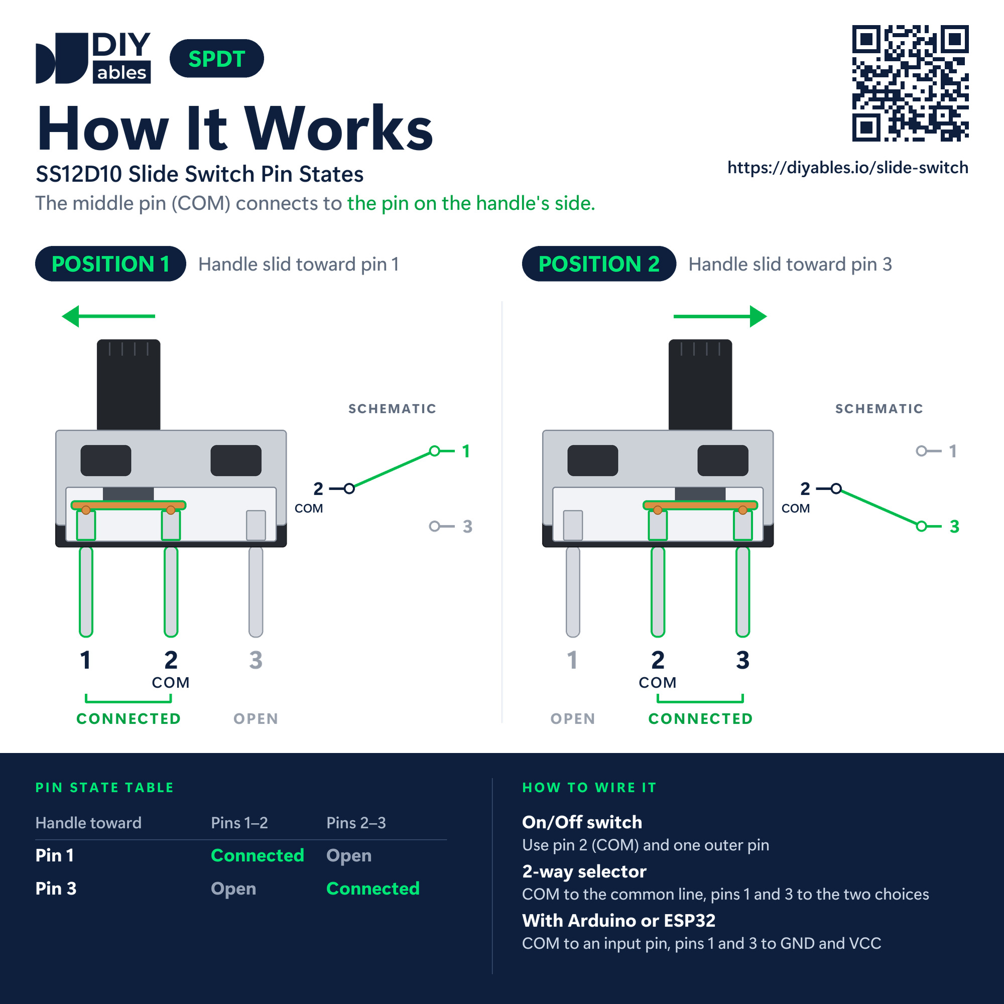
You have seen this kind of switch on the side of toys, flashlights and small radios. The DIYables Mini Slide Switch SS12D10 is a little rectangular block. A short handle (5mm) sticks out of its top, and its three legs stand in one line at the bottom. You move the handle sideways, and it clicks into one of two positions. Then it holds that position by itself, with no power and no finger needed. Compare that with a push button, which counts as pressed only while you hold it down. In shop listings, the switch type is written as 1P2T or SPDT (single pole, double throw). In plain words: the common leg is linked to one of the two other legs at a time.
How does it work? The handle carries a small metal bridge. One end of the bridge sits on the middle leg (pin 2, COM) all the time. The other end follows the handle and lands on the outer leg on that side.
| SS12D10 Slide Switch | |
|---|---|
| Switch type | SPDT (1P2T) |
| Positions | 2, the handle stays where you leave it |
| Legs | 3 in one row, vertical through-hole |
| Leg spacing | 4.7mm |
| Leg length | 6.9mm |
| Handle | 5mm |
| Body size | about 12.8 x 6.7 x 18.2mm |
| Contact material | silver-plated brass |
| Contact rating | AC 125V 2A |
| Switching life | more than 100,000 cycles |
| Temperature range | -25°C to 80°C |
About the AC 125V 2A line: that is the upper limit of the contacts, not what they see here. On the NodeMCU, far less than one milliamp flows through them, and the voltage never goes above 3.3V.
The Slide Switch Pinout
The switch has no pin names on it. Start counting at either end:
- Pin 1 (outer leg): must be connected to a G (GND) pin of the NodeMCU
- Pin 2, COM (middle leg): must be connected to a GPIO of the NodeMCU that can work as an input. This tutorial uses D7 (GPIO13), which then follows the level of whichever outer leg the bridge reaches
- Pin 3 (outer leg): must be connected to 3V3 when you use three wires. When you use two wires, it stays empty
The two handle positions from the picture:
- Position 1, handle at the pin 1 end: pin 1 and COM are joined, pin 3 is open. With the wiring below, D7 reads LOW, which we call OFF.
- Position 2, handle at the pin 3 end: COM and pin 3 are joined, pin 1 is open. D7 reads HIGH, which we call ON.
※ NOTE THAT:
How do you tell the legs apart with no labels? By position only: COM is always the center leg of the row. The two outer legs are twins. If GND and 3V3 land on the opposite outer legs, nothing gets hurt; the sketch just prints ON with the handle at the other end.
Wiring Diagram
In the diagram, the NodeMCU and the slide switch are plugged into the same breadboard. Each wire starts in a hole right next to the board pin it needs and ends in a hole of the matching leg's column: the middle leg goes to D7, pin 1 goes to G, and pin 3 goes to 3V3. Whatever the handle position, COM ties D7 firmly to either 3.3V or 0V. Since D7 is never left open, no extra resistor is needed in this circuit.
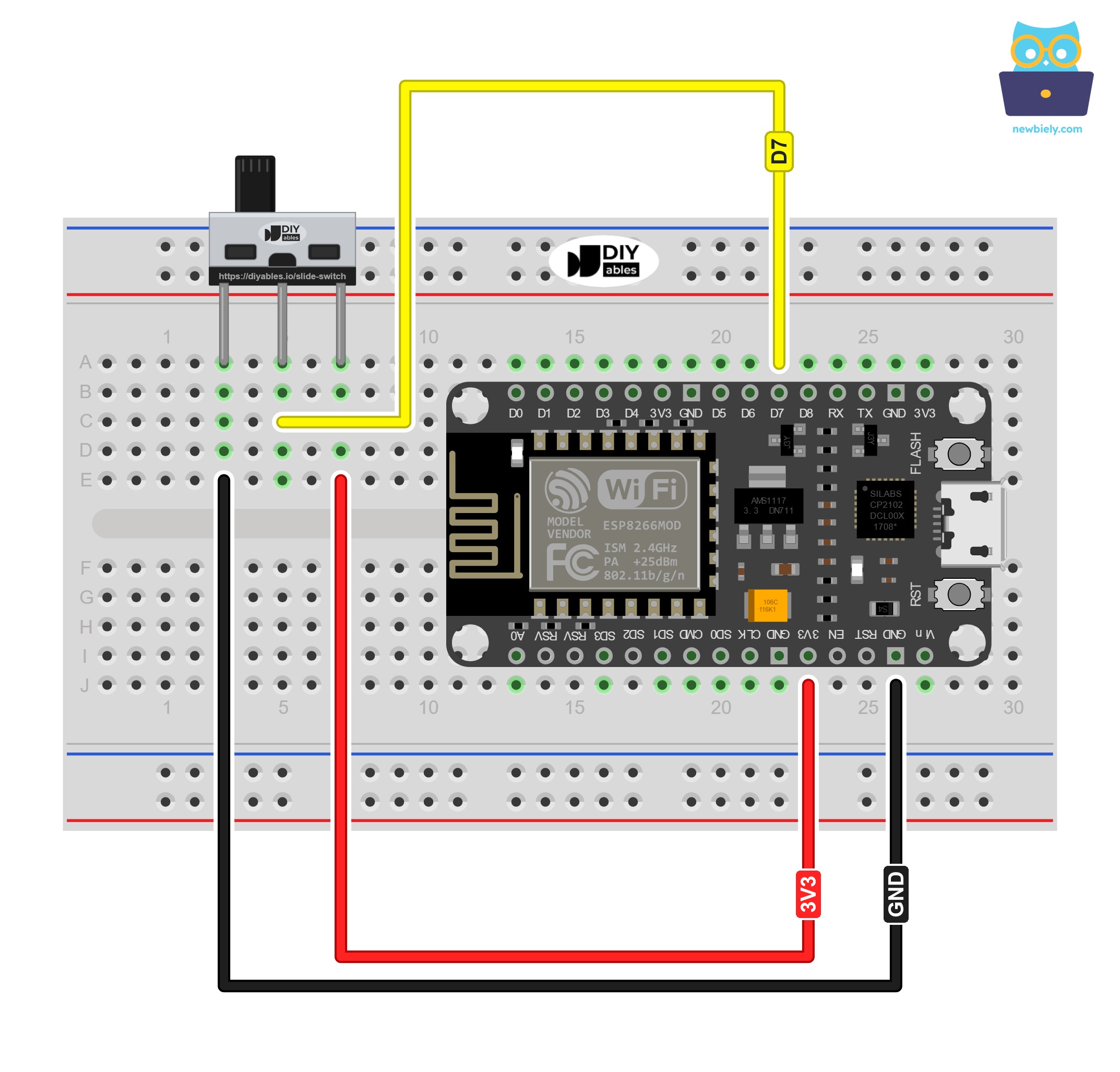
This image is created using Fritzing. Click to enlarge image
| Slide Switch Pin | ESP8266 NodeMCU Pin |
|---|---|
| Pin 1 | → G (GND) |
| Pin 2 (COM) | → D7 (GPIO13) |
| Pin 3 | → 3V3 (not VIN) |
WARNING
Use the 3V3 pin for pin 3 of the switch. VIN and every other 5V source are off limits. Whatever voltage sits on pin 3 reaches D7 directly as soon as the handle points that way, and the GPIO pins of the ESP8266 work at 3.3V only.
D7 must stay an input pin. Do not call pinMode() with OUTPUT for it: one handle position connects D7 to 3V3 and the other to GND, so a pin that tries to drive the opposite level would make a short circuit.
Want to move COM to another pin? D5, D6, D1 or D2 will do. Keep the switch off D3, D4 and D8: the ESP8266 checks these pins while it boots, and a slide switch keeps its level all the time, so the wrong handle position can stop the NodeMCU from starting. For the 2-wire version, also skip D0 (GPIO16), which has no internal pull-up resistor. After a change, update the SLIDE_SWITCH_PIN line in the code. A full pin table is in Additional Knowledge.
How To Program For Slide Switch
No library is needed. The ESP8266 core for Arduino IDE already has every function used below.
- The first step is to tell the sketch which NodeMCU pin the COM leg is on. The ESP8266 core knows the board labels, so D7 can be written directly; it stands for GPIO13:
- Inside setup(), make the pin an input with the pinMode() function. Plain INPUT fits the 3-wire wiring, because the two outer legs never leave D7 without a level:
- Then, the digitalRead() function returns the handle position: HIGH at the pin 3 end (ON), LOW at the pin 1 end (OFF):
- Last, deal with bounce. When the handle slides, its contacts rattle open and closed several times within a few milliseconds. So if a reading differs from the stored setting, pause for 50 milliseconds, take a second reading, and accept the new setting only if that second reading agrees.
This simple delay() check is enough for a switch that moves now and then. For a debounce that never pauses the loop, see ESP8266 - Button - Debounce.
ESP8266 NodeMCU Code for Slide Switch - 3-Wire Version
Right after boot, setup() looks at D7 one time and prints the starting setting. From then on, loop() prints nothing while the level stays the same. When the level changes, it waits out the bounce, checks the pin again, and writes exactly one line for the move.
Detailed Instructions
- New to the ESP8266? Set up Arduino IDE first with how to setup environment for ESP8266 on Arduino IDE.
- Build the circuit from the diagram: COM on D7, pin 1 on G, pin 3 on 3V3.
- Plug the ESP8266 NodeMCU into your computer with a USB cable.
- Open Arduino IDE on your computer.
- In the board menu, select NodeMCU 1.0 (ESP-12E Module). In the port menu, select the COM port that appeared when you plugged in the NodeMCU.
- Start a new sketch, paste the code above, and press the Upload button.
- Start the Serial Monitor at a speed of 9600 baud.
- Leave the handle on the pin 3 side, then press the RST button on the NodeMCU. The first line shows the setting at boot.
- Now make three moves: handle to pin 1, handle to pin 3, handle to pin 1.
After you press RST, a few strange characters may show up above the first line. They are the ESP8266's own boot messages, sent at another baud rate (74880). You can ignore them; the empty Serial.println() in setup() starts the real output on a new line.
Lines keep appearing although your hands are off the switch? A loose G or 3V3 wire leaves D7 open, and an open pin picks up noise. No new line at all when you move the handle? Check that D7 goes to the center leg; an outer leg never changes its level.
ESP8266 NodeMCU Code for Slide Switch - 2-Wire Version with INPUT_PULLUP
Is the 3V3 pin of your NodeMCU already crowded with sensor wires? Or will the switch sit at the end of a long cable, for example in the lid of a box? Then try this version. On the ESP8266, GPIO0 to GPIO15 each come with a built-in pull-up resistor, and pinMode() with INPUT_PULLUP enables it for D7. Unplug the wire from pin 3, and the hardware is ready. COM stays on D7, and pin 1 stays on G.
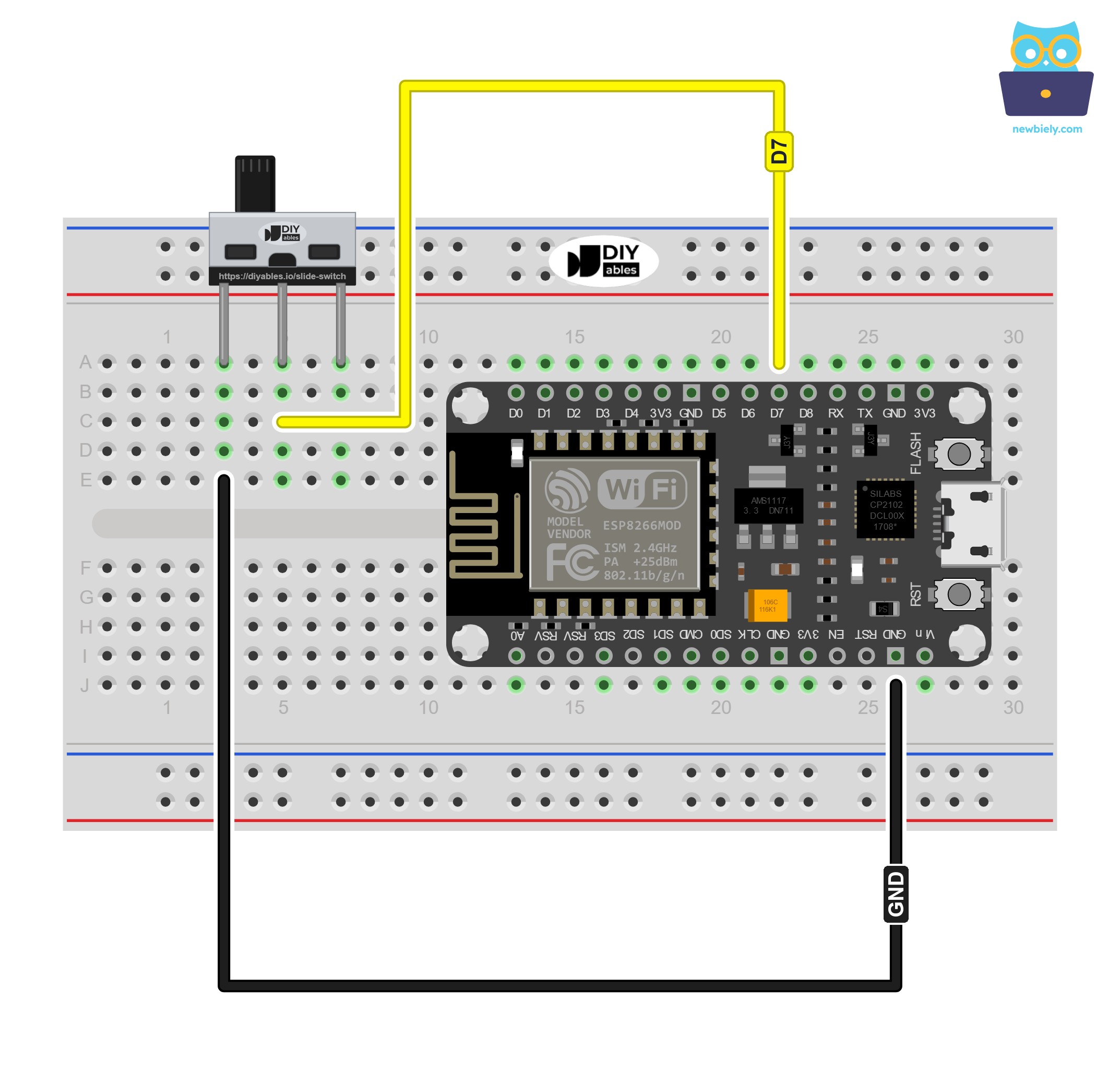
This image is created using Fritzing. Click to enlarge image
See more in ESP8266's pinout and how to supply power to the ESP8266 and other components.
| Slide Switch Pin | ESP8266 NodeMCU Pin |
|---|---|
| Pin 1 | → G (GND) |
| Pin 2 (COM) | → D7 (GPIO13) |
| Pin 3 | not connected |
Watch out, because the two levels swap their meaning. A LOW reading is now ON: with the handle pushed toward pin 1, COM connects D7 to GND. A HIGH reading is now OFF: with the handle pushed toward pin 3, COM leads to the empty leg, and the built-in resistor pulls D7 up to 3.3V. The comments at the top of the code say the same.
Detailed Instructions
- Take the 3V3 wire away from the switch. The other two wires do not move.
- Replace the first sketch with the code above and click Upload again.
- Open the Serial Monitor (9600 baud) and press RST. Your last move left the handle on the pin 1 side, and this time that side prints ON.
- Make four moves: handle to pin 3, to pin 1, to pin 3 and to pin 1.
Same handle, same place, opposite word: at the pin 1 end, the first sketch printed OFF, and this one prints ON. That is how INPUT_PULLUP works, not a fault.
Additional Knowledge
Which NodeMCU Pins Can Read a Slide Switch?
| NodeMCU Pin | GPIO | 3 Wires (INPUT) | 2 Wires (INPUT_PULLUP) | Note |
|---|---|---|---|---|
| D1 | GPIO5 | Yes | Yes | also the usual I2C SCL pin |
| D2 | GPIO4 | Yes | Yes | also the usual I2C SDA pin |
| D5 | GPIO14 | Yes | Yes | free unless you use SPI |
| D6 | GPIO12 | Yes | Yes | free unless you use SPI |
| D7 | GPIO13 | Yes | Yes | the pin used in this tutorial |
| D0 | GPIO16 | Yes | No | no internal pull-up resistor |
| D3 | GPIO0 | Avoid | Avoid | must be HIGH at boot, LOW starts flash mode |
| D4 | GPIO2 | Avoid | Avoid | must be HIGH at boot, also drives the on-board LED |
| D8 | GPIO15 | Avoid | Avoid | must be LOW at boot |
| RX, TX | GPIO3, GPIO1 | Avoid | Avoid | used by the Serial Monitor |
| A0 | - | No | No | analog input only |
It is evident that D1, D2, D5, D6 and D7 are the safe homes for a slide switch on the NodeMCU. A push button touches a boot pin only for a moment, but a slide switch holds its level all the time, also at the moment the ESP8266 starts. So a boot pin is a risky place for it.
Ideas for Using the Slide Switch
- Web lock: while the switch is OFF, the NodeMCU web page can show the relay state but cannot change it.
- Unit selector: a WiFi thermometer shows °C with the handle at one end and °F at the other.
- Quiet mode for a WiFi doorbell: the chime stays silent, but the phone message still goes out.
- Update guard: the NodeMCU accepts a new firmware over WiFi (OTA update) only when the handle is on the ON side.